NB: Present
days, Cars with high speed engine I air-condirioning compressor-drives
have (till date) no alternatives but to use Cogged Belts since:
- Limitations in pulley size with obvious high RPM.
- Generation of heat in covered area for compressor running in
conditioning the air inside the Car.
A comprehensive list of application in
automotive under Indian Subcontinent ( as per list)
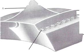
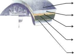
(A.) SECTION AND SIZE- Since section and size of the belts in so
many areas are reciprocal to automobile manufactures of the World;
it is advisable for the Foreign - Buyer to either suggest the total
size - Top Width x Thickness x Length (1/c,O/C,PL) orthe Code No.,
on the Belts.
(B.) POLYESTER DIPPED CORD - Properly heat-set and simultaneously
rubberized polyester cords are built in, Under tension to prove
maximum bending frequency without variation on load. Of course
different no. of plies of PFY are used in compatiation towards
section
(C.) INSULATION COMPOUND - The same compound with Synthetic Rubber
is applied in Traction Layer and Compression Rubberto privide high
Heat Resistance and Flexibility and Bonding in totality.
(D.) BASE (COMPRESSION) RUBBER COMPOUND - High Heat, Abrasion-Resistant
Compound for compromising the compression the load, bonding and
provide smooth running.
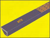
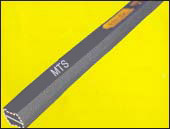
" BLACK TIGER" MTS BELTS
ARE MANUFACTURED IN O/C.
- Slabs ofthe specific Thickness and length in O/C.
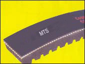
- Thickness and Coggs and are maintained to generate and assure
FLEXIBILITY - Cogged Format gives higher flexibility resulting in
efficient dissipation.
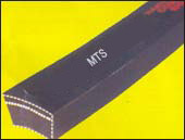
Strong Tensile Member and Transverse Modulus provide high Horse - Power Rating.
Special Rubber Compound becomes high Heat Resistant, Special Homogenlousity on
total shape and Ultimately smooth running.
INSTRUCTIONS FOR PROPER USE
OF
MTS V-BELTS
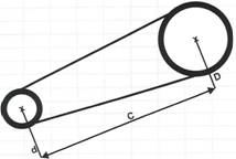
ALIGNMENT
After installing the belts, it should be checked that the pulleys
are properly
aligned. Failure to do so will reduce the drive and shorten the V-Belt
life.The
diagrams here show some of the common mis-alignments.
***Do not use belt dressings.
*** Normal V-belts will withstand temperature
upto 70°C working temperature above this level can shorten
belt life.
*** Belt overloading is a sure sign offaulty drive
design. Do not try to increase power transmission by applying more belt
tension; this will only cause belt rupture and is likely to harm the
shaft bearings.
*** In case of replacing the whole set must be
replaced instead oftrying to fit in a new belt.
** Drive must be equipped with belts of the correct
type and size: as well as the number necessary to transmit
design
power. Belt cross-sections and sheave grooves must match.
***Sheaves
must be in perfect alignment and grooves free from rust, dirt and
burrs.
***After running in for about 15 minute at full
load, the belts will have seated in the grooves. At the same time
they will have stretched by about 0.5% to 1 % of nominal length.
After retightening, belt tension must be checked periodically,
since slip caused by slackness will soon destroy the belts.
*** Guard belts against oil, grease, solvents
etc.
Storage: V - Belts should be stored in stock room and contact with
hot pipes and direct sunlight carefully avoided. Where possible handle
the belts loosely in single or triple coils. Always avoid tying them
tightly with spring.
Installation: In assembling a drive, the motor should be moved towards
the driven unit, so that the belt may be placed in their respective
grooves by hand. The belt should not be forced on the pulley with
screw drivers, wedges, crow-bars or any other type of implement.
When the belts have been placed in the pulley grooves, the motor
should then be moved away form the driven unit to apply uniform tension
to the belts.
MTS V-BELTS CONFORM TO INDIAN & INTERNATIONAL
STANDARDS
i.e.
IS-2494, BS-3790,DIN-2214, 2215, ISO 4184, RMA IP-22
FOR
ALL THE PROPERTIES. |